
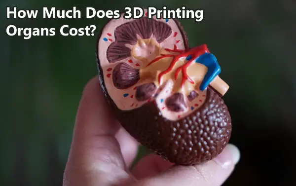
Currently, thousands of people are waiting on the transplant list for organs like kidneys, heart, and liver. Unfortunately, there are not nearly enough donor organs available to fill that demand. You also cannot donate an organ such as a heart while the patient is alive. What if instead of waiting, we could create a brand new customized organ? That is the idea behind bioprinting.
This technology is still in development but there are already printers out there capable of performing the impossible a few years ago. The consensus is that rather than printing cells layer by layer as in regular 3D printing, 3D printing of organs should be done by printing scaffolds on which cells can grow and develop into a full size organ.
As you can imagine with such an undertaking on the cutting edge combining 3d printing technology, medicine and biology, this is not something that comes at a low price. Let’s discuss the costs of printing organs.
The cost of 3D printing organs is changing as technology evolves. Living tissue has been successfully printed with a $1000 3D printer while more specialized bioprinters cost upwards of $100,000. Other costs involved include bioinks which start at hundreds of dollars, associated research and the cost of highly skilled operators for 10 weeks or more per organ. It is not uncommon for the initial cost of bringing a bioprinting technology onto the market to be in the tens of millions of dollars.
According to the National Foundation for Transplants, a standard kidney transplant can cost up to 300,000 dollars. But compared to that if a kidney is printed through a printer and if they are suitable for use in the human body then the cost will be much less. Companies such as Bioscience, Volumetric, FluidForm, Printivo are working on 3D-printed organ services.
It is not all easy going, and companies pioneering in this space have to face huge start up costs in the millions of dollars to bring their technology to market. Operating losses can be very high. Funds are usually obtained from grants and private investors. Another limitation is getting through all the usual red tape and testing tissue first in animals and finally in humans years later if approved.
What are 3D printed organs made of?
The world of 3-dimensional bioprinting or 3D organ printing is very complex. Polymers such as Hydroxyapatite, Titanium, Chitosan, and collagen are used that need to be biocompatible and capable of having cells attach to their scaffold and grow into an organ.
BioInk:
A bioink, which can be thought of as printer ink for bioprinting, is a a hydrogel material combined with cells. Using bio-inks provides high reproducibility and precise control over the fabricated constructs in an automated manner.
Bioinks are able to support the growth of various cell types. They come as a ready-to-use gel for printing 3D tissue models. They are versatile and biodegradable. BioInk is usable for long-term tissue cultivation such as many weeks.
OsteoInk:
Calcium Phosphate material for 3D tissue printing is called as OsteoInk. OsteoInk is a ready-to-use calcium phosphate paste for structural engineering. OsteoInk is a highly osteoconductive biomaterial close to the chemical composition of human bone. It is used to make various types of hard tissues in the human body such as bones, cartilage, or structural scaffolds.
OsteoInk can be combined with BioInk to create complex 3D tissue mimetic models. It controls the uniqueness of the bioprinter by enabling freeform fabrication of the tissue model, creating tissue layers, pore formation, and biological structure. BioInk is often used with OsteoInk to reduce opacity.
In addition to BioInk and OsteoInk, special ingredients like Agarose, Collagen, Alginate, Polyethylene, Glycol, and Gelatin are used for 3D Bio-printing.
Why is printing organs difficult?
Transplantation of 3d printed organs could be a revolution in medical science. However, many issues stand in the way. Researchers are working hard to create a directly replaceable organ. Many companies are working day after day to make it possible. They are constantly facing many problems while doing this research. As with organ transplants in the human body and rejection, the recipient often faces some problems. What are those unresolved obstacles? Let’s see what problems scientists have to go through in this work.
Limited options for Biomaterials:
Collecting the biomaterials that are used to support and structure the cells that make up a functional printed organ is a difficult task for scientists.
As mentioned earlier, Synthetic polymers and Hydrogel are used for 3D organ printing. Synthetic polymers are mechanically strong and suitable for printing but may lack cell adhesive properties to support cell growth. Meanwhile, natural polymers are not as strong as synthetic polymer polymers but are much more suitable for cell attachment, expansion, and differentiation.
Scientists have recently printed a heart using a 3D bioprinter. The main ingredient in the artificial heart was Alginate, and it was taken from a type of algae that lives in the deep sea. They chose nano cellulose and alginate because these plant-based materials naturally support the power of plant micro-architectures to aid cell growth.
Maintaining the shape of the soft material:
The key to printing three-dimensional functional organs is to maintain the structural integrity of the organ. The shape of the artificial organ often depends on the viscosity of the BioInk used in the printer.
Biodegradable scaffolds made from biomaterials have often been used to maintain the shape of bioprinted tissues and seed cells, but scaffolding defects include stimulating immune responses, as well as cell detachment from potential toxicity and decay by-products.
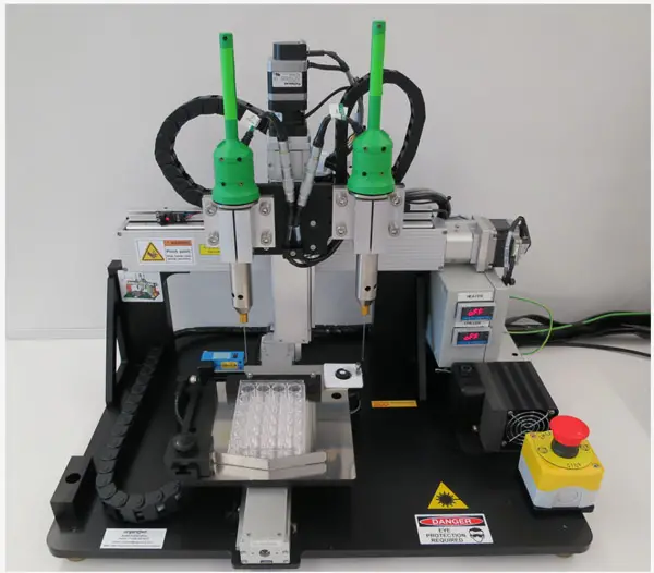
Bioprinters:
Printers have become one of the major problems for bio-printing. Some minor flaws in the use of printed organs in the human body can become a major problem. Often, the entire printing is ruined due to a printer hardware error. An error in organ printing occurs when the printer is interrupted for some other reason.
Below is a good TED Talk video on how bioprinting works:
Which 3D printers are used for organ printing?
Bioprinting can be done with inkjet based and extrusion based methods, as well as SLA, FDM and SLS.
BioInk is used as the main printing material for 3D organ printers. A bioprinter uses polymeric materials and cellular hydrogels, such as syringes or professional extrusion paste. But plastics are used as the printing material of ordinary printers. So a bioprinter should never be compared to a normal printer. Currently, many companies are working on making and improving bioprinters.
Bioprinters are available at different price points and qualities on the market. The bioprinter made by ‘EnvisionTEC’ is the latest type of a bioprinter. This printer converts computer-aided tissue engineering 3D models and patient CT data into a physical 3D scaffold. This printer is called ‘ 3D Bioplotter’.
The ‘NovoGen MMX’ made by Organovo is a much better quality bioprinter. They have created this for their own use only. This bioprinter is only used to make beneficial tissues. Organovo does not sell its ‘NovoGen MMX’ technology.
“Organovo BioPrinter” by NIH-NCATS is marked with CC PDM 1.0
RegenHU’s ‘3DDiscovery’ bioprinter is one of the most expensive printers. The printer uses two printing methods and utilizes various hydrogels, bioactives, cells, and extracellular matrix materials. It is capable of enabling dynamic protein networks as well as cell/cell interactions.
These are very advanced printers. Also, there are some less expensive printers available in the market. Typically, these start at 10,000 dollars. But, buying a good quality printer can cost up to 200,000 dollars. One of the less expensive printers, ‘Alpha & Omega’ is a 3D printer made by ‘3Dynamic Systems’. It works on syringe-based extrusion technology.
Developers are still working on some sophisticated and open-source models of 3D printers, which have not yet hit the market. However, the hope is that when they come on the market, 3D bioprinters can be used at a very low cost and open to all.
Here is a price guide for some of the more expensive bioprinters.
Other uses for 3D printing in medicine
3D printing technology is very important in the field of medical science. 3D-printed organs have been used in many large and complex surgeries as reference. From the human brain to the smallest bones of the body, 3D printing has been used. 3D printed anatomical models are important for medical improvement. Surgeons can take less time in surgery by planning and practicing an operation on a custom 3d printed copy of a patient’s organ.
I hope that this article has given you some idea about what is involved in 3D printing of organs, including the costs. Click the following link to learn how to 3D print wax.
Medical Imaging vs. Radiology: What’s the Difference?
Unless you are a trained medical professional, you may have trouble understanding the difference between medical imaging and radiology. It’s sometimes hard to differentiate between two similar ideas or practices within the medical field, and people often get these terms confused.
In this article I will describe each term in depth and explain how they differ.
While radiology and medical imaging are certainly very closely related, they are not the same thing. Radiology is the science of X-rays and other high-energy radiation technologies for the diagnosis and treatment of different conditions and diseases. Medical imaging technologies, on the other hand, are visual representations of the inside of the body.
Radiology, however, is not limited to just one area of practice. Below, I will highlight several different specialties and subspecialties that utilize different medical imaging techniques for various purposes.
Is Medical Imaging and Radiology the Same?
While medical imaging and radiology are very closely related and often are confused with each other, they are not the same thing. Radiology is a specific field of medicine, while medical imaging is a technology used by radiologists. Medical imaging may be used by radiologists to monitor, diagnose, or treat various conditions within the body in a non-invasive way. Different types of radiologists specialize in and utilize different medical imaging technologies, depending on what field of medicine they’re in and what kind of patients they treat.
These technologies are used so physicians can view the inside of the body without needing to perform any exploratory surgeries. According to the FDA, this is crucial in allowing the radiologist and other doctors on a patient’s care team to learn and monitor information related to the diagnosis and treatment of diseases or injuries. It also allows physicians to check how the body is responding to previously administered medical treatment.
What is Medical Imaging?
The term “medical imaging” refers to a branch of technologies that allow a radiologist to diagnose, treat, or monitor diseases or injuries inside the body. It can also be used to keep track of the body’s response to a previously administered or ongoing medical treatment.
According to NPS MedicineWise, medical imaging includes technologies such as:
- X-rays
- Ultrasounds
- CT Scans
- MRIs
- SPECT Scans
- PET Scans
Each of these technologies is best suited to different purposes, depending on the patient’s condition and what part of the body the radiologist needs to view.
Types of Medical Imaging Technologies
There are many different types of medical imaging technologies that radiologists use. Here is what you can expect with each one:
X-Rays with Ionizing Radiation
X-rays are typically used to provide images of the bones inside your body. They use ionizing radiation and are most often used to tell if you have a bone break or sprain. They can also detect arthritis, osteoporosis, infections, cancer, or digestive problems.
X-rays are relatively quick and simple, taking just a few seconds to complete. Usually, an x-ray will be done while you are either standing or sitting, but you might be required to lay down in some instances.
CT Scans with Ionizing Radiation
CT scans take a series of X-rays to create images of the cross-sections within the body. Like x-rays, they use ionizing radiation and can detect broken and fractured bones, infections, and cancers. According to the University of Virginia, CT scans can:
- Detect traumatic injuries
- Detect vascular and heart diseases
- Guide biopsies
While x-rays are typically done while you’re sitting or standing, and are only done while laying down in certain circumstances, a CT scan requires you to lay on a table that slides into a tube, rotating around you while it takes x-rays of your whole body.
Like x-rays, CT scans are fairly quick procedures. They take about 15 minutes to complete, though this can vary based on your condition.
MRIs with Magnetic Waves
Like CT scans, you’ll be required to lay on a table that slides into a scanner during an MRI, though MRI machines are usually more narrow and deeper than CT scanners. MRI machines use magnetic waves, and you may hear tapping or banging while the MRI is used.
These scans produce detailed images of organs and tissues. According to UVA, MRIs can detect and diagnose serious conditions and problems including:
- Aneurysms
- MS
- Strokes
- Spinal cord issues
- Tumors
- Joint and tendon injuries
Ultrasounds with Sound Waves
Most people are familiar with ultrasounds in terms of monitoring a pregnancy and checking an unborn baby’s development. However, ultrasounds also have a number of important diagnostics uses. The University of Virginia claims ultrasounds can guide biopsies and diagnose things like:
- Blood flow problems
- Joint inflammation
- Breast lumps
As the name suggests, ultrasounds use sound wave technology to view different organs within the body.
When you get an ultrasound, the technician will first apply a gel to your skin to reduce the amount of air between your skin and the ultrasound probe. This is done because the ultrasound waves may be affected while traveling through the air, skewing the image they provide. The technician will then move the probe around the area until they find the area they need to see.
PET Scans with Radiotracers
Positron emission tomography (PET) scans are one of the more complicated medical imaging technologies. They use radioactive drugs called “radiotracers” to show organ and tissue function throughout the body.
Before you undergo a PET scan, you’ll need a dose of radiotracers. The radiologist will either give you a radiotracer pill to swallow or an intravenous injection of the substance prior to the scan, and this will allow the scanner to read the radiation given off by it.
PET scans can be used to diagnose a variety of serious conditions, including:
- Cancer
- Heart diseases
- Alzheimer’s
- Parkinson’s
- Epilepsy
The machine used to administer a PET scan is similar to those used for CT scans and MRIs.
SPECT Scans with Radiotracers
Single-photon emission computerized tomography scans, or SPECT scans, are a type of nuclear imaging scan similar to PET scans. They produce images that show how well your organs work together, like how well your blood flows throughout your body or what areas of your brain are the most active.
According to the Mayo Clinic, SPECT scans can monitor and diagnose:
- Heart disorders
- Brain disorders
- Bone disorders
Before the SPECT scan begins, you will be given an intravenous dose of a radiotracer similar to that administered during a PET scan.
Once your body has absorbed the substance, you will be scanned in a machine similar to an MRI machine. The length of time it takes can vary depending on your condition, but it’s typically a longer process than most other medical imaging procedures (Mayo Clinic).
What is Radiology? What are the Different Types?
Radiology is a branch of medicine that uses radiation technology, including medical imaging, to diagnose, treat, and monitor diseases and injuries. In some cases, radiology is also known as roentgenology.
Physicians who practice radiology are known as radiologists. They may specialize in one of three areas:
- Diagnostic Radiology
- Interventional Radiology
- Radiation Oncology
Within the broader area of radiology as a whole, there are three distinct areas in which radiologists will practice, according to the American Board of Radiology. These areas include:
Diagnostic Radiology: Diagnosing and Treating Disease
As the name suggests, diagnostic radiology is mainly concerned with the diagnosis and treatment of disease. Diagnostic radiologists use all of the medical imaging technologies listed above in their work.
There are many subspecialties that diagnostic radiologists may work within. Some of these include neuroradiology, pain medicine, and pediatric radiology.
Interventional Radiology: Using Medical Imaging for Treatment
Interventional radiologists perform imaging, image-guided procedures and can diagnose or treat conditions within:
- The abdominal region
- The pelvic region
- The thorax
- The extremities
They may utilize therapies such as embolization, angioplasty, drainage, and stent placement in their work.
Interventional radiologists may subspecialize in a variety of subjects, including nuclear medicine and pediatric radiology.
Radiation Oncology: Treating Cancer with Radiation
Radiologists who practice radiation oncology use radiation technologies, including ionizing radiation, CT scans, MRIs, and ultrasounds to treat cancer.
People who receive radiation therapy for cancer treatment will typically be working with a radiation oncologist. They may also use hyperthermia, or heat treatment, in their work. Some subspecialties of radiation oncology include hospice and palliative medicine, and pain medicine.
Different Subspecialties within Radiology
Subspecialties are specialized areas within the three main branches of radiology. Diagnostic radiologists, interventional radiologists, and radiation oncologists all have different fields in which they may subspecialize. There are also a number of intersectional subspecialties that include radiologists from all three backgrounds.
These are the subspecialties in which a radiologist might have expertise in:
Hospice and Palliative Medicine: Providing End-of-Life Care
Radiologists in all three fields are able to subspecialize in hospice and palliative medicine. These radiologists help to prevent and ease the suffering of patients who have been diagnosed with life-limiting illnesses, such as late-stage cancer. They work to optimize a patient’s quality of life and may also offer support for families.
Neuroradiology: Treating the Neurological System
Neuroradiology is a subspecialty often practiced by diagnostic and interventional radiologists. Neuroradiologists work within the neurological system, which includes the brain, sinuses, spine and spinal cord, neck, and central nervous system.
Neuroradiology can help treat:
- Aging and degenerative disorders
- Cerebrovascular diseases
- Cancer
- Other traumatic injuries or conditions.
Radiologists in this field commonly use medical imaging techniques such as angiography and MRIs (American Board of Radiology).
Nuclear Radiology: Using Radioactive Substances for Medical Imaging
Nuclear radiologists typically work within the diagnostic and interventional radiology fields. These physicians use small amounts of radioactive substances, including radiotracers, to create images and get information to render a diagnosis. They typically use PET, and SPECT scans to do so (American Board of Radiology).
Nuclear radiology can be very helpful in treating thyroid conditions, including hyperthyroidism and thyroid cancer. It is also often used to treat other kinds of cancer, including lymphoma, and can help with the pain brought on by cancer (CDC).
Pain Medicine: Easing Pain with Radiation Therapy
Diagnostic radiologists, interventional radiologists, and radiation oncologists may all have a subspecialty in pain medicine. These physicians provide pain relief care for all patients, including those with acute, chronic, or even cancer pain, in both in-patient and out-patient environments. They also work closely with other types of doctors to properly coordinate a patient’s ideal pain relief regimen.
Pediatric Radiology: Safely Providing Radiology for Children
Pediatric radiologists in the diagnostic and interventional radiology fields diagnose and monitor congenital disorders, and those present mainly in children and infants. They also work with children who have conditions that can cause more problems later in life.
An important part of a pediatric radiologist’s job is making sure all imaging techniques, including x-rays, CT scans, MRIs, and nuclear medicine, are administered properly and safely enough to treat young children.
Vascular and Interventional Radiology: Treating Vascular Conditions
Diagnostic radiologists have the option to subspecialize in vascular and interventional radiology. These physicians use a variety of medical imaging techniques to diagnose and treat disease, including:
- CT scans
- MRIs
- Digital radiography
- Fluoroscopies
- Sonographies
Vascular and interventional radiology is used to treat conditions like cardiovascular disease, cancers, and even varicose veins therapies used by these subspecialists include:
- Stent placement
- Drainage
- Angioplasty
- Embolization
Benefits Offered by Medical Imaging Technology
Experts agree that medical imaging is one of the most widely beneficial and useful medical developments in recent history. The New England Journal of Medicine has even ranked medical imaging as one of the top medical developments of the past 1,000 years!
Below, you’ll find a list of some of the top benefits offered by medical imaging technology:
Early Detection of Diseases and Other Conditions
Medical imaging by radiologists has made it possible for doctors to detect diseases much earlier on in their progression. This is especially useful for asymptomatic conditions, or those that show no outward symptoms. When doctors are able to catch a harmful disease earlier, there’s more that can be done for the patient treatment-wise.
Most health issues are much easier and less expensive to treat in the earlier stages, while those caught late tend to require expensive, intense treatment or invasive surgeries.
One example of how early detection with medical imaging has saved countless lives is digital mammograms. Digital mammograms are used to detect breast cancer and can catch signs of it an average of two years before a tumor would even begin to form. This gives those affected less invasive and a greater number of options for their next step.
Quicker, More Reliable Diagnoses
Medical imaging procedures can render a faster and more accurate diagnosis, because the radiologist can actually see what’s causing a problem. It’s also far safer than having the patient undergo an unnecessary exploratory surgery and can help doctors better determine when surgery is actually needed.
Most medical imaging requires little to no special preparation. With CT scans, you may be asked not to eat anything less than four hours prior to the scan, and PET and SPECT scans will require you to either take a small dose of radiotracers orally or intravenously.
Barring special circumstances, these are the only preparative measures that need to be taken prior to a medical imaging procedure.
Better Monitoring of Known Conditions
Medical imaging can also help radiologists, and other types of physicians better monitor the progress of known conditions and how well these conditions are responding to ongoing or previous treatment.
Diagnostic imaging is painless and non-invasive, so patients who suffer from conditions that need to be monitored will be subjected to less invasive procedures, including exploratory surgeries. This can, in turn, reduce the length of time a patient spends in the hospital for their condition.
Imaging technologies can show if and how a condition is progressing, how it’s responding or not responding to treatment, and the severity of any internal injuries, like bone fractures.
Medical animation, biovisualization and medical illustration
The terms medical animation, biovisualization and medical illustration are sometimes confused with medical imaging. Medical animation is the process or product of creating a 3D educational film about a physiological process or other medical topic, which often includes models built from scratch. Biovisualization is the process of representing biological data visually and may include processing medical imaging data. Medical illustration is the process or product of creating any illustration including 2D and 3D visuals of biological and medical topics and may encompass medical animation.
Each of these may be based on or include data and images acquired through medical imaging technologies.
What are Radiologists’ Credentials
Becoming a radiologist will require medical degree, along with the proper licenses and certifications for your state. According to CME Science, you’ll need a Doctor of Medicine (M.D.) or Doctor of Osteopathic Medicine (D.O.) to become a radiologist.
After graduating with from medical school, many prospective radiologists, or radiology technicians as they’re sometimes called, choose to do a radiology residency at a hospital. This may or may not be required, depending on your state, but could be helpful in making connections and building your resume!
After all your training is complete, you’ll need to pass a state exam to become a licensed radiologist. This exam varies by state and may require you to complete a certification program with the American Registry of Radiologic Technologists.
Even if your state does not require this certification for licensing, it may be beneficial to do so anyway to increase job prospects.
Below is a useful introduction to medical imaging from the University of Buffalo:
Final Thoughts
While the terms medical imaging and radiology tend to be used interchangeably, they are far from the same thing. Radiology refers to the use of radiation technologies to diagnose and treat diseases and injuries, while medical imaging is a subset of these radiation technologies used by radiologists.
Radiologists may specialize in many different areas, but all radiologists use medical imaging to one degree or another.
Click on the following link to learn how to improve the quality of MRI images.
Maya vs. 3ds Max: Which is Better for Modeling?
Maya and 3ds Max are two of the most popular software options available for people interested in 3D modeling for medical animation. Due to their extreme popularity and vast resources, it can be difficult to choose between the two for modeling purposes.
Let me get into the topic of choosing a software package for modeling, define what the differences between the two programs are in this aspect, and offer some advice.
Both Maya and 3ds Max are incredible tools for 3D modeling. Both programs are just as capable as the other, and the main choice will come down to preferred workflow and additional needs. 3ds Max is easier to learn, while Maya offers expanded options through advanced scripting.
For the purposes of medical animation, both programs are capable of producing highly accurate and detailed models. 3ds Max is known to have a shorter learning curve, but exploring some of the specific pros and cons of each piece of software may help in coming to an informed decision.
Is Maya Good For Modeling?
Maya is certainly near the top of the list for most powerful 3d applications available. It is perfectly suited for a variety of modeling, animation, rendering, and simulation. Essentially any part of the 3d image creation process can be completed in Maya, making it a powerful suite in its own right.
Focusing on 3d creation as a whole, Maya is known to have a variety of tools introduced in recent builds that make modeling easier. Maya is powerful enough to successfully create any 3d model, but the tools available may make it more frustrating than other options for complex creations. While the capability is there, Maya’s workflow when it comes only to modeling can be confusing, especially for beginners.
However, this is a problem that Maya has been fixing ever since its 2014 release. Features such as remesh, sculpting, and polygon modeling are standard in the current version and allow for detail to be easily added. More information on the current modeling toolset can be found here, on Maya’s website.
Specific Tools For Modeling In Maya
There are many tools that have been directly integrated into Maya to make it a more powerful 3d modeling tool. While the focus of Maya is still firmly planted in animation and rendering, these extra features provide the program with enough power to serve as the 3d modeling software of choice for many medical animation needs.
Of the available tools, some of the most relevant ones for medical animation are:
- Remesh
- Retopologize Features
- Sculpting Tools
Each of these specialized tools allow for additional detail or quicker access to technical changes that improve workflow and make modeling easier. With some creativity, everything can find a home in any workflow.
Remeshing
Remeshing in Maya is a quick way to select an area and break down its components into smaller triangles, allowing for more detail when working on the selected piece. For example, a human ear may consist of 50 or so surfaces; a remesh application will split these pieces further into triangles, creating an additional 50 or even more surfaces. As surfaces decrease in size and increase in number, more detail can be added and structured. This is essential for creating models of intricate or small areas.
Retopologizing Features
The retopologizing feature is a quick way to clean up any unevenness or missing areas of any model to improve efficiency and ensure the conservation of detail. Cleaning up a model after painstakingly creating it can take an enormous amount of time but is essential to create accurate models, essential for medical animation. This tool takes out much of the pain of the procedure.
Sculpting Tools
Sculpting tools are now commonplace across almost every 3d modeling software, but some sets of tools are better than others. Sculpting tools take the process of digital 3d modeling and transform it into something more similar to working with clay or another physical object, allowing for some artistry to be injected into the workflow. Sculpting tools are incredibly useful for creating organic models.
Pipeline Integration
One of the strongest reasons to choose Maya is for it’s incredible integration capabilities into other workflows. Depending on what other programs you may use for 3d animation, Maya has flexible tools that allow for easy file and data transfers. Even if the specific program you use is not inherently supported, Maya supports a small handful of scripting languages to allow for custom plug-ins that make exporting easier.
Thanks to Python and Maya Embedded Language (MEL) support, Maya can seamlessly fit into almost any existing workflow. There is also a large community of active Maya users who share plug-ins online and are willing to help newcomers become acquainted with the software at large as well as its advanced features.
Python is the most popular programming language in the world and is commonly praised for its flexibility and low barrier of entry. Learning Python expands Maya’s modeling capabilities almost directly, as some of the missing 3d modeling tools that users may want can be custom-coded in.
MEL is a proprietary scripting language that was designed for easy integration into the Maya software. This is the most popular scripting language for Maya, as it has been around for almost the entire lifetime of the program. Custom plug-ins supporting exporting into various programs, defining new modeling tools, or ease-of-life shortcuts can be found all over the web.
More information on the specifics of scripting in Maya and a glimpse into the power it provides can be found here.
Here is a useful video on Maya modeling:
Is 3ds Max Good For Modeling?
3ds Max is arguably the quintessential 3d modeling program, designed from the ground up with usability and modeling workflow in mind. While Maya excels at other aspects of the digital 3d creative space, 3ds Max undoubtedly has more tools and pipelines for pure modeling purposes.
3ds Max sees use in architecture, game development, historical recreations, and, of course, medical animation. The tools are explicitly robust enough to accommodate any 3d modeling needs. Thanks to the program’s extreme focus on modeling capability, even beginners should be able to quickly get into the swing of things and start creating.
3ds Max comes equipped with a variety of advanced tools that can speed up any pipeline and make modelers feel more confident in their workflow. Many tools found in Maya, such as sculpting and remeshing, are also standard. The main difference between Maya and 3ds Max when it comes to modeling is the existence of features which decrease wait time and allow for constant creation.
Advanced Modeling Features of 3ds Max
3ds Max has many features that make specific tasks in 3d modeling much easier. While many similar results can be achieved with Maya through its advanced scripting languages, there is something to be said for how easy 3ds Max makes the process in comparison.
To a beginner, some of these tools may seem needless or as if they barely save anytime at all; however, as you grow more accustomed to 3d modeling and venture into more advanced tasks, a little bit of creativity with some of these features can save an enormous amount of time.
Some of the modeling and texturing features that 3ds Max offers include:
- Spline workflows
- Baking to texture
- Weighted normals modifier
Spline Workflow
Spline workflows can fundamentally change how 3d modeling occurs thanks to it’s intelligent design. Simply put, spline has a variety of functions that all center around cutting out time spent on basic tasks. Things such as mirroring a design, morphing and blending between shapes, soft selecting and editing areas, and line smoothing are simple quality of life improvements that drastically improve how easy it is to create using 3d models. These even mesh seamlessly with sculpting tools and other aspects of 3ds Max to make modeling intuitive.
More information about the various functions that Spline workflows offer can be found here, alongside detailed documentation.
Baking To Texture
Baking to texture is a scripting-based function that creates a library of texture maps to apply to 3d models. This library can then be accessed quickly using scripts, allowing for textures to be approximated while modeling is happening.
This is extremely helpful while trying to line up objects, complete final edits, and generally get a good look at what the finished product may appear as. Under traditional workflows, textures would not be able to appear on the objects during edits – instead, lighting would have to be rebuilt, materials recompiled, etc. This cuts work time significantly and creates a great environment for quick edits.
Baking to texture can get even deeper than surface level textures, even including the ability to bake UV tiles while editing. However, for most people, this type of functionality will prove unnecessary.
Weighted Normals Modifier
Weighted normals are meant to improve the shading of models and the bouncing of light actively, as edits occur. This functionality is similar to the aforementioned baking to texture, but only touches upon lighting. It also smooths it out quickly so that less load time needs to occur.
With this functionality, lighting can be quickly edited, moved, deleted, or replaced and the effects will happen in close to real time. Lighting can also be blended at various intervals and edges can be detected.
This is most useful for creating complex scenes with lots of different light sources, as may happen when mapping out a complex medical model.
There are a variety of other tools and time-saving technologies built into 3ds Max that really make it a pleasant experience for almost anyone looking to 3d model. However, it does lack in some other areas where Maya takes the lead. Subjects like animation, rendering, and pipeline integration are all better suited for Maya.
Considering both are more than capable of tackling almost all 3d modeling needs, other factors should also be considered.
Below is a good video on 3ds Max modeling:
Community Support
3ds Max is the more popular choice for purely 3d modeling, meaning that more plug-ins, support, and tutorials are available online. Specifically, there are many downloadable plug-ins that are specifically meant to make modeling easier that can be found and applied to a variety of workflows.
Where many of Maya’s plug-ins focus on animation or rigging, 3ds Max plug-ins are meant to improve modeling even further. Taking advantage of the sleek and easy to parse UI, many users may also have an easier time getting used to 3ds Max plug-ins.
Animating in 3ds Max or Maya
Although I am focusing on modeling here, animation is an important thing to consider, especially since many models, even those for prototyping, are often animated in the end . Whether creating a video walkthrough or description of a part of the body, showing the layering of muscles and skin, or creating a walking or healing animation, the animation needs are endless.
While 3ds Max has the edge for modeling, Maya takes the lead when it comes to most aspects of animating 3d models. Thanks to a robust toolset that incorporates a variety of rigging and quick animation features, the workflow for animating in Maya can be much faster.
As with modeling, the truth is either program can achieve similar results. Instead, it is best to look at which program is easiest to use for the intended purpose and which has more tools available. In that regard, once again, Maya wins.
Applications of Animation For Scientific Purposes
There are plenty of areas where animation is useful. While exporting models to an alternative program for animation can be done, it’s often beneficial to be able to outline the basic movement of various 3d models in the same program before shipping out for additional effects.
One of the most common medical uses for animation is for education. Creating a 3d model of any part of the human body is hugely beneficial, but adding the ability to walk through and explore various parts in video format can be even more so.
Even without large animations, the ability to move various pieces of a 3d model and introduce transitions or motion graphics can elevate any 3d model and make it more visceral, professional, and useful. Both 3ds Max and Maya can be used for this purpose and more.
Motion in either program can be broken down into two parts: rigging and animation. Rigging is often wrapped up into the larger category of animation as a whole, but both are equally important in adding some movement to any 3d model.
What Is Rigging?
Rigging is the process of attaching points of movement to 3d models where animation can occur. When applied to human models, it is often called a “skeleton”, where the various joints are placed as underlying moving elements. For instance, a pumping heart, a breaking bone, or a moving machine. Any area of a model where movement will occur receives a rigging element or joint.
The basics of rigging stay the same across almost any 3d modeling software, but some specific tools available in either Maya or 3ds Max can make the process easier.
Many modern advancements in rigging are meant to automatically find points by detecting the geometry of the model or organize nodes and connections to declutter rigging, as it can quickly get complicated.
What Is Animation?
Animation is the act of making 3d models move. This is done through the use of keyframes; the model is positioned one way using rigging and assigned a keyframe on a timeline. Then, the model is moved to the next position/pose and assigned a later keyframe on the same timeline. For example, a walking animation is created by starting the person as still, then moving the hip, arms and legs and adding another keyframe.
Good animation requires setting enough rigging, moving the correct parts, and establishing a proper timing of keyframes. A walk where the person only moves their legs will look unnatural, and if it’s too slow people will notice something looks strange. This is applicable to every animation.
The animation program will detect the changes between keyframes and try to automatically fill the frames in-between with movement. If there are too few keyframes, this will look unnatural and the program is likely to make mistakes. Likewise, too many keyframes take up a significant amount of time and memory for little to no benefit.
3ds Max Animation
Animation in 3ds Max is highly capable of producing beautiful and effective work, but many nice tools are missing or require significant plugins to get working.
For basic animation, as is often common for medical technologies, this program is likely to serve more than well enough. However, those looking for more powerful animation or an easier workflow may wish to turn to Maya.
3ds Max focuses on providing the basics of animation and rigging in a simplistic and easy to parse way. Its features are largely limited to basic timelines and procedural animation tools, but occasionally, they slip in additional features that are worth taking a look at. One such feature is the 3ds Max Fluids technology, which allows for realistic liquid behavior that responds to gravity and collisions. More about this feature can be found here.
Many of the specific animation tools that 3ds Max provides are focused around character animating, which is not always used in medical animation. However, with some ingenuity and a little bit more elbow grease, it will serve any necessary animation functions perfectly.
Some of the animation tools that 3ds Max provides include:
- Motion paths
- Particle flow effects
- Animation layers
Motion Paths
Motion paths are a feature that let you preview the path of animated objects. For instance, if blood pumping through arteries is being animated, the path of the blood will appear and is editable to achieve the desired result. This is most useful when combined with the aforementioned spline capabilities of 3ds Max, so a path can be built directly into the model.
The majority of the time, a motion path is useful for working out details of motion when it requires a specific path or area to stay in. Animating the movement of a swallowed object through the throat is an example where motion paths may be useful. More information on motion paths and their use can be found here.
Particle Flow Effects
Particle flow effects are extremely powerful and can be used in a myriad of situations. The technology behind effective particle flow is fairly complicated, but the basics involve individual objects being defined by shape and speed.
Once the thousands of individual objects have been generated and defined, they are moved and interact with each other and other models in the space to create effective movement.
The particles constantly interact with each other and react to the environment, creating a natural look for things such as smoke, liquids, or semi-solid substances. Essentially, anything that can flow can use particle flow effects to achieve a realistic movement animation.
Medically, this is applicable to a wide variety of uses, such as showing blood movement, displaying liquid medicine, the filling of the lungs, or other uses.
Animation Layers
3ds Max employs animation layers to overlay multiple tracks on top of each other, either for testing purposes or to combine animations into one, larger result.
This is most useful for iteration and the editing of animations; simply copy the existing animation into a new layer, hide it, and edit on the original. This way, if something goes wrong or you are unhappy with the results, you can quickly revert back to the first copy.
While not as intuitive as Maya’s nondestructive editing environment, it does offer many of the same benefits. Merging layers is also highly beneficial for working out any kinks in animation if you have multiple layers that look great at different points.
Maya Animation
Animation in Maya revolves largely around scripting in either Python or MEL, its proprietary language. Luckily, a deep knowledge of these languages is not required to achieve fantastic results and gain access to the incredible number of tools that Maya provides.
In spite of the need for scripting, Maya’s animation still holds the crown for ease of use when compared to 3ds Max. This is largely due to MEL being incredibly easy to customize and learn – a few hours in an afternoon are enough to set up almost anyone with enough knowledge to do most animations they desire.
What the language doesn’t immediately cover can be quickly found online, as there is an incredible rigging and animation community around Maya. Tutorials covering the various parts of Maya, custom plug-ins for specific types of animations, and additional resources for practice are all easy to find.
In addition to having every basic tool needed for animation, Maya takes the lead for the various tools it has to speed up workflow or introduce advanced techniques in an easy to parse way. Tools such as:
- Cached Playback
- Animation Bookmarks
- Motion Library
- Nondestructive Time Editor
All allow for quick edits and changes to animations that allow for easy iteration and speed.
Cached Playback
Cached playback is one of the important features of animating in Maya. This allows for you to see changes made to an animation immediately, rather than waiting on Maya to redraw and render everything out.
Especially with large animations, this rerendering could take significant time. It works by saving the animation scene in multiple parts. When edits are made, Maya only needs to reload that specific slice instead of the whole thing. You can read more about it here.
Animation Bookmarks
Animation bookmarks allow for specific splits of time to be saved on the timeline for various animations for quick revisiting.
These bookmarks are not linked to any specific keyframes, but are instead linked to another function of Maya called the Time Slider, where animations can be scrubbed through like a video. This is highly useful while making quick edits to an animation and comparing the results.
Motion Library
Maya has recently introduced native support for a motion library plugin of various capture data of people moving and completing various daily tasks. This is a game changer for a variety of fields, as gaining access to natural movements and automatically rigged models is a common challenge.
While less relevant for medical animation, this quick library is a great example of what can be done with plugins for Maya, and the models can be used for details or background in a variety of cases.
Nondestructive Time Editor
Finally, Maya’s animation sequence editor is non-destructive, so edits can be made without losing parts of the animation that were previously created. This is similar to a video editor where, when a cut is made, the video that has been cut off still exists in case further edits need to be made.
Maya’s editor is a powerful tool for all parts of animation that is sure to see significant use for any required animation work. It is here on the timeline that important facets like timing, speed, length, and keyframes are defined. The fact that the timeline is non-destructive is a fantastic bonus for all professionals, but especially beginners who may make more mistakes than others.
Choosing Between The Two Programs
Choosing between the two programs for general modeling and animation needs can be difficult. Truthfully, it’s hard to make a wrong choice; they are both wonderful and capable pieces of software that can help any professional elevate their work. However, as a general rule, 3ds Max is better for modeling, and Maya is better for animating.
I hope you enjoyed this article. Click the following link to learn if 3d modeling is hard to learn.
Rigging in Animation: What Is It and Why It Matters
In the world of 3D medical animation, there is an entire jargon that can leave the average person confounded. Computer animation design-centric terms such as NURBS, bezier, rigid bodies, and follow through are a few examples that will likely send most people to the search engine. On this list is rigging. What is rigging in animation, and why does it matter?
Let’s analyze.
Rigging (or skeletal animation) is a way to build the underlying structure of a character or other articulated object using series of interconnected digital bones or “joints”. The hierarchical set of interconnected joints collectively forms the skeleton, or rig, of the object. Therefore, the process for creating the bone structure of a 3d model is known as rigging, and it can be used to help manipulate a 3D object like a marionette puppet similarly to how a skeleton would act in real life.
When making the model, designers can see the bones of the rig via computer software using a 3D view, but the bones are hidden beneath the mesh when the final model is put into action. By creating this invisible skeleton, rigs add an element of control to the animation process as they help solidify a model’s constitution and avoids deformities in the character they create.
Computer software allows rigging artists to view their renderings from several perspectives, allowing them to spot potential deformities in the animated character’s bone structure before the animation is recorded. Some key points that rigging artists will be looking out for when designing their 3D skeleton include:
- Number of joints – joints in rigged skeletons are very similar to the joints in a human skeleton—they guide and control movement. With this in mind, the rigging artist will want to add more joints in the areas of the model that demand a higher degree of control, as fewer joints in the model will lead to more mechanical movements.
- Rig hierarchy – for the end motion to be realistic, the rig must be designed logically. As rigs operate under a parent/child relationship, the corresponding joints must be created in the proper size and scale. For example, the shoulder joint should supersede the elbow joint, which should supersede the wrist joint.
- Inverse kinematics (IK) built into the rig – while the logical hierarchy of the rig takes precedent, it is also essential for the rigging artist to rig for inverse kinematics. This is the process through which the motion of the skeleton works opposite of logic. For example, for an animated character to demonstrate a push-up, the child wrist joint should remain while the parent’s elbow joints move.
- Control curve opportunities – the rigging artist can help the animator by grouping a set of rigged joints together using a control curve. This cluster of grouped joints has its control placed outside of the rigged skeleton. It allows the animator to move the entire group of joints in a single motion without individually manipulating each bone.
Based on this information, it can be seen how the rig for an animated character works in much the same way as the skeleton supports a human body. The digital bones in the rig act together to create virtual tissue that defines the movement of an animated object. This interconnected digital tissue creates a hierarchical environment in which the movement of a parent joint triggers movement in the “child” joint of the model unless the skeleton has been rigged for inverse kinematics.
It is a useful process for animation because rigs can create life-like motion of a model. Animators can then use the rig to help control the motions of the 3D model. As a result, the rig gives animators unprecedented control, flexibility, complexity, and fluidity of motion over more primitive animation techniques—all vital characteristics for effective medical animations.
When executed correctly, the rigged skeleton will bind seamlessly to the organic mesh, making the animated character’s motion highly convincing. This is an improvement over animation processes in which control over each individual body part/individual 3d object is required.
How Does Rigging in Animation Work?
Pretty much any type of object can be rigged. This has made it a popular technique in the entertainment industry, as it has helped modern cartoons display more life-like renderings of characters than more primitive animation techniques.
This application applies equally well to the medical field. For example, medical animation professionals can use rigging in animation to create realistic interpretations of bones, joints, and organ systems. This can allow practitioners to create accurate simulations of how the body will behave.
It can also be highly beneficial when paired with 3D printing technology. For example, practitioners often have to create specialized prosthetics for specific patients, so having the ability to animate the prototyped piece in a digital simulation before execution can help eliminate much of the guesswork and trial and error associated with newly fabricated materials.
The following breakdown looks at how rigging fits into the overall process of medical animation:
Surface Representation is Created
Prior to rigging, a model of the object must be created. Therefore, designers will create what is known as the surface representation of the object. Within the CAD world, this surface representation may also be referred to as the mesh or the skin. To the casual observer, the mesh may look like nothing more than a drawing of an arm, a leg, or bust. That’s because the mesh, by itself, is nothing more than a model. As a surface representation, it needs some bones to give it life. This is where rigging comes in.
Skeleton is Assembled and Transformed
Once the mesh is in place, a skeleton is created to fit within the mesh. This may be a group of backbones, arm, leg, head bone, spine—basically any part of the body that matches the sketch the medical animator is trying to recreate.
After the bones of the skeleton have been put in place, designers can use animation software to transform the skeleton. This means that the position, rotation, and scale of the bones can be changed.
In a process known as keyframing, these transformations are recorded along a timeline, with these recorded instructions resulting in an animation of the 3d model.
How Rigging Improves the Animation Process
Rigging is an essential technique in the animation field because it allows computer designers to make realistic motion and deformation. By effectively using rigging techniques, modern 3D animation is far superior to traditional animation and stop motion animation, especially when precision in the medical field is necessary. Several factors allow rigging to yield superior animated renderings.
Hierarchical Instructions
Throughout the keyframing process, the recorded movements create a set of hierarchical instructions that the computer will repeat when moving an animated object. In this hierarchical structure, each bone in the rigged skeleton is part of a parent/child relationship with the other bones to which it connects in the rig, just like in a real organism. For example, if a hip bone is moved, the femur, knee, shin, and foot will all move as a result of these hierarchical instructions.
This simplifies the animation process for designers as it limits the number of instructions that they ultimately have to write and allows the animated object to imitate real life as accurately as possible.
Weight Painting
How the mesh interacts with the rig will be determined by a weight scale. Each bone within the model will control a certain amount, or weight, of mesh. Therefore, without some fine-tuning to the weight scale, some distortion in the animation may occur if certain bones within the rig carry too much influence over a particular section of the mesh.
A technique known as weight painting is used to effectively distribute the necessary portion of the skeleton to an assigned section of mesh. While the computer can often perform weight painting, some of the more intricate weight distribution challenges must be handled manually by a design professional. While sometimes difficult to master, weight painting is critical in eliminating distortion from the animation.
Movement Constraints
Programming movement constraints are another essential element in ensuring that an animated image moves smoothly. To guarantee smooth movement, the animation software must be programmed to restrict certain types of movements from particular bones. For example, a knee must be programmed with the constraint that it can only bend backward. This again reflects nature.
Why Rigging is Important in Medical Animation
As mentioned, eliminating costly trial and error, and helping perfect best practices without consuming resources are a couple of the benefits of rigging in animation. However, there are many other benefits of how the realistic models created by rigging can improve the medical industry.
Medical Simulation
There are a finite number of cadavers in the world on which doctors can practice their procedures. As a result, animation provides a potential solution to this shortage. However, the animation must depict a 100% accurate rendering to have any value, making the smooth, life-like interpretations of rigged 3D models the best choice.
Rigged 3D animation also has a potential wide-reaching impact on the medical school industry. Many students are scared away from school due to the high price tag associated with laboratory and hospital training fees. If rigged 3d animation becomes universally adopted as a medical simulation tool, it may make medical school more accessible to a broader pool of candidates.
Cellular and Molecular Animations
Much of what we know about cells and molecules has been learned from under a microscope. While different types of animation have been used throughout the years to depict cellular processes in more convenient realms, rigged animation can create motions that are true to the cell.
Processes that 3D animation can help recreate include interplay between organelles, transcription of DNA, the molecular action of enzymes, the interaction between pathogens and white blood cells, and virtually any other sub-molecular process imaginable.
Pharmaceutical Mechanism of Action
Adopting pharmaceutical products can often be delayed when medical decision makers must digest their possible theoretical effects. To help in this regard, pharmaceutical manufacturers may use rigged animation to provide action clips that help explain how a medication will work.
Emergency Care Instruction
Regardless of how much training a caregiver has received, it is often impossible to accurately simulate emergencies in a safe yet instructive manner, but rigging in animation can make this possible. Using animation in this way, novice practitioners can get a realistic look at how to administer CPR, abdominal thrust, mouth-to-mouth, AED, and other emergency care techniques.
Surgical Training
In addition to medical school training, rigging in 3D animation allows experienced surgeons to hone and expand on their craft. Whether by attempting new, risky, or vanguard procedures, surgeons can combine animation with virtual reality to practice their procedures without experimenting on patients.
Weaknesses of Rigging in Animation
Although rigging has allowed for superior control, fluidity, and complexity of motion in animated models, allowing for the most realistic animated characters possible, a couple of potential weakness have been pointed out:
- A rigged skeletal system only represents a set of vertices and, taken independently, cannot accurately replicate the complexity of the human body
- The realistic motion of the muscles and skin is only attained through the use of deformers and other secondary features
Best Practices of Rigging in Medical Animation
Although the section above expounded the exciting ways in which rigging in animation can be used in the medical field, it must be executed with 100% accuracy to make the animation admissible. As a result, whether you are a 3d designer contracting with a medical facility or creating animation in-house on company software, there are several important tips to help ensure that rigged animations turn out as accurately as possible.
Map Out Actions First
It is impossible to effectively rig an object without any idea about what that object will do. As a result, before placing a single bone, you must sit down and draw out a map of all action that needs to be animated.
It is best to start planning by assuming that the model will need to perform a broad range of motion. This can be achieved by adding more joints to the rig. As the number of joints increases, the range of possible motions will increase exponentially. This is vital in ensuring that characters in the animation are flexible, move smoothly, and can perform complex motions.
A best practice in the medical animation industry is to create a rig that can perform all of the same movements that a human can. This will allow your object to adapt to any unexpected events in a simulation.
Don’t Over Rig the Object
Although the importance of adding multiple joints for a broad range of motions was just mentioned, it is also essential to avoid over rigging an object.
As the rigger and animator are often separate entities for most projects, talk to the animator and determine exactly what the animated model will be used for. Suppose the animation is intended to simulate an operating room procedure for knee surgery. In that case, you do not need to waste valuable time implementing complex facial rigs for the animated patient.
Ensure that the Rig is Properly Scaled
The correct anatomical placement of bones and joints is critical for animation in the medical field. While this may seem like common sense, cartoons and other types of entertainment animation may try to create surreal effects with their characters, so be sure that the placement of all body parts is scaled to ensure anatomical accuracy.
Without the correct anatomical rigging, the animation will appear distorted. Two exceptions to this rule are the knee and elbow joints. You will want to rig these joints a little closer to the skin instead of directly in the center of the limb to create the realistic protrusion that occurs when the joint is bent.
Use Deformers for Facial Rigging
The standard rigs used for bones and joints throughout the body will not work when rigging the face, as the eyebrows and cheekbones will require a stretchier, more organic rig.
Deformers can help in this regard. A deformer is a set of computer algorithms that can “move large sections of a model to simulate organic shapes and movement” with greater accuracy than standard rigs.
For example, with eyebrows, you could run a wire deformer along the brow to create precision when conveying emotion. If you need to create wrinkles in your character, a cluster deformer may be a strong bet, as cluster deformers allow the animator to control many vertices at once.
Take Advantage of All Perspectives
When building the rig, use multiple camera views to ensure that the rig fits the skin along all three dimensions. This should not be too difficult, as 3D animation software has grids that will allow you to judge the size and shape of the skeleton within the mesh.
Make sure to use a front view, bird’s eye view, and profile view. Taking advantage of these different perspectives allows you to pick out any anomalies in your rig—especially those that could potentially create a deformation.
The Best Rigging Software for 3D Medical Animation
While the virtues of rigging in animation have been extolled for its ability to create the most life-like animations in the industry, it is critical to choose the right platform to get the most out of potential rigging capabilities.
While 3D animation packages will come with rigging capabilities as part of the bundle, each will have subtle differences that may or may not appeal to your particular needs. The following are some great products that can help you effectively incorporate rigging techniques into your facility’s medical animation efforts.
- Moka Studio – In addition to having support for motion capture techniques that can be applied to rigs, allowing for increased realism and faster development, Moka Studio has rolled out new technology for controlling rigged characters in real-time.
- Maya – This is the industry standard for 3D animation. Used by the largest number of animators across the country, many rigging artists are adept at providing top-notch rigs on this platform. It provides all of the essential elements required for rigging a realistic medical model and is intuitive to navigate for less experienced riggers.
- Blender – This is an open-source animation software that is totally free. This makes it a strong choice for entities exploring the power of rigging in animation for science. While Blender has all of the tools necessary to rig and animate a model, it is not quite as powerful or comprehensive in its features as Moka Studio or Maya.
- Mixamo – This is another strong option for novice rigging artists and an excellent product for professionals looking to rig their objects on the fly. Mixamo automates the rigging and weight painting process so that you can quickly see what your models look like in action. The platform also offers a host of default rigs that can be customized to create original object motions.
- MakeHuman – MakeHuman is a strong platform for creating generic human-like characters. It can be beneficial in a medical setting because it allows you to quickly customize models based on height and weight, with the product automatically rigging the model once these dimensions are inputted.
Below is a good video on human model 3d rigging by James Taylor:
Conclusion
Rigging in animation, or skeletal animation, is a computer animation technique used to represent a 3D object using a series of interconnected digital bones. It is essential in medical animation because, when properly deployed within a skin, quality rigs can allow the animator to control the model like a puppet, creating flexible, realistic designs unmatched by any other animation technique. Such animation offers a host of cost-effective benefits that have the potential to improve the medical industry through life-like simulations.
I hope this article has helped you understand rigging better. Click the following link to learn how to bake animation.
How to Improve the Quality of Your MRI Images
Whatever your end use of MRIs is, its very important how good the MRI images are. Unfortunately, it is a common scenario to have to repeat the scan due to poor quality MRI images.
But how do you improve the quality of your MRI images to avoid these unnecessary, avoidable situations?
Improving MRI images can be done by addressing and understanding each factor that influences quality. The four main factors to consider are:
- Image resolution
- Signal-to-noise ratio (SNR)
- Contrast sensitivity
- Artifacts
The right configuration makes all the difference in capturing the best quality MRI images no matter how outdated or advanced the MRI machine is. You will want to read on further as the next few sub-topics are the most critical information that you will need to help enhance your skills in taking excellent images.
What Is the Resolution of an MRI Scan?
According to a research study published by Cher Heng Tang, from the Department of Diagnostic Radiology in Tan Tock Seng Hospital, most MRI scanners have an approximate resolution of 1.5 x 1.5 x 4 mm3. Meanwhile, Ultrahigh Magnetic Field (UHF) MRIs have resolutions of up to 80 x 80 x 200 μm3.
How to Optimize Image Resolution?
First off, it is essential to define image resolution and break down what constitutes it. Image resolution refers to the details we see in an image. The higher the resolution, the better distinction can be shown between structures.
Image resolution can be adjusted according to these three aspects:
- Slice thickness
- Image matrix
- Field of view
Understanding Slice Thickness
Slice thickness refers to the amount of tissue that can be sampled in each slice. To achieve a better resolution, slice thickness must be decreased to create sharper images. The recommended thickness setting should be 1 to 1.5 mm.
What Happens if I Increase Slice Thickness?
Increasing slice thickness would make the tissue denser and more compressed in one slice. In this setting, it is also possible for other adjacent tissue types to be included in the slice. This often results in partial volume artifact that yields blurred MRI images.
What is Partial Volume Artifact?
Partial volume artifact produces a blurred MRI image that results from an overlapping of tissues of different absorption or signal intensity. The newest MRI scanners are now equipped with a technology that could reduce the volume of a voxel, significantly dropping the issue of this artifact interfering.
What is an Image Matrix?
An image matrix is defined as a grid of pixels in 2D MRI or voxels in 3D MRI each represented in squares or rectangles. To have a better understanding, let’s define what makes up a pixel or a voxel first.
Pixels Vs. Voxels
A pixel refers to the smallest element in a 2D image. On the other hand, Voxel, derived from the words “volumetric” and “pixel”, represents the pixel and thickness in a 3D space. Adjusting the matrix manipulates the number of pixels or voxels whereas changing the field of view adjusts the size of the pixels or voxels.
- It’s important to remember that the size of the pixels/voxels is inversely proportional to the resolution. The smaller the pixel/voxel, the higher the resolution of an image.
- On the other hand, the number of pixels/voxels present in a matrix is directly proportional to the resolution of the image. The more pixels/voxels present in a matrix, the higher the resolution.
How Do You Adjust the Pixels?
The pixels or voxels can be modified by making adjustments in the columns and the rows of the grid known as the phase direction and the frequency direction. The phase direction represents the columns of the grid, whereas the frequency direction refers to the rows of the grid.
To get a better image resolution, you must increase the values of both directions to increase the number of columns and rows present in a matrix. By raising the number of columns and rows, more pixels or voxels will make up your image.
Isotropic Vs. Anisotropic
To create a perfectly squared pixel, the phase and frequency must be at an equal value. In a voxel, the phase direction, frequency direction, and slice thickness must bear the same values. This is called an isotropic pixel or voxel.
On the other hand, when the frequency value is greater than the phase value, it creates a rectangular pixel, otherwise known as anisotropic. The phase direction can never be more than the frequency direction as this will create longer scanning or imaging time, which can make the resolution drop.
Field-of-View and Its Effects
The field of view refers to the area size that the image can cover. This is similar to zooming in when snapping a picture on your phone.
When you zoom in, you are able to isolate and focus on your subject by excluding from the image its surroundings. However, the image becomes more pixelated as pixel size increases, which often translates into a blurry picture. When you zoom out, more pixels are able to fit in your field of view as the pixel size becomes smaller, creating a sharper image.
How to Set the Field of View to Improve Quality of an Image?
Adjusting your field of view will also depend on the body section of interest. When a specific section of the body needs to be focused, a smaller field of view must be set. When a larger section needs to be scanned, such as in an abdomen, a larger field of view will make the scanning easier.
In many MR scanners, the largest field of view that can be set is approximately 50 cm each in length, width, and thickness.
To achieve a higher image resolution, the field of view must be decreased. However, it is important to know that this kind of setting lowers the signal intensity.
What is Signal Intensity?
Signal intensity is held by each pixel or voxel collected from the patient. The larger the pixel/voxel, the higher the signal intensity it carries to accurately map the most specific details of the body part. However, a higher signal often means a lower resolution.
How Does Signal-to-Noise Ratio (SNR) Affect Image Quality?
In any type of imaging, noise always exists. Image noise, as a result of some sort of interference (frequently electronic) shows up as a grainy pattern on images. In an MRI, the primary source of noise can come from the patient’s body due to emission of radiofrequency from the movement of charged particles within the body. The coils and electronics of the MRI can also contribute to image noise.
Moreover, it’s important to emphasize that noise is not synonymous to artifacts, which we will discuss in detail moving forward.
How to Set SNR
To reduce the noise, the signal must be greater than the noise. Certainly, increasing the signal-to-noise ratio reduces the noise but will lower the image resolution because higher signal means bigger pixels/voxels. Thus, to achieve a higher resolution image, SNR must be set in the “low acceptable limit.”
How to Reduce Image Noise
A lower SNR means a noisy image. Fortunately, there are ways that you can reduce the noise in your images:
- Reduce the basic resolution
- Lower the slice thickness a bit
- Use a wider field of view
- Increase the number of voxels in the matrix
- Decrease bandwidth of pulse sequence
How to Improve Signal
A lower signal often yields blurry images. Fuzzy images tend to obscure important details of the image. To prevent your MRI images from appearing blurry:
- Increase the basic resolution
- Decrease the field of view
- Reduce the number of voxels in the matrix
It’s a matter of finding the best configuration in the middle to avoid overly grainy or overly blurry images.
What is Contrast Sensitivity?
Contrast sensitivity refers to the differences that each tissue projects to allow them to be distinguished from one another. MRI is superior in terms of contrast sensitivity compared to other forms of imaging because of its capability to visualize differences among the tissues.
How Does Contrast-to-Noise Ratio (CNR) Affect Image Quality?
Contrast-to-noise ratio is defined as the differences between the signal intensity (SNR) of two adjacent tissue types relative to the image noise. When the CNR is increased, it gives the viewer a perceived distinction between the two tissue types because of a higher SNR difference, thereby improving the image quality for physicians to make a clinical diagnosis.
With that being said, the CNR is influenced by the same factors that influence SNR. Thus, when you want to improve the CNR, you should look into the same methods that improve the SNR.
There are three physical parameters that can influence signal contrasts:
- p
- T1
- T2
This topic is very complex and takes an explanation that is too long to be adequately summarized here. If you want to read more about how these parameters can affect the signal contrasts, you can read further in this lecture.
How Do MRI Artifacts Affect Image Quality?
MRI artifacts are interference in an image that often project as streaks or spots that do not represent any clinical significance. Often times, artifacts are associated with body movement when the patient is not able to lay still during the imaging. It can also be due to environmental factors such as heat emission or humidity.
From an untrained set of eyes, it’s easy to misinterpret artifacts as something of clinical importance. When artifacts appear, this lowers the quality of your image. So, it’s important to point out the source to address the issue.
MRI artifacts categorized into three causes and some of the most common examples of each cause:
| Inherent physical or tissue-related artifacts | Hardware or technique-related artifacts | Physiologic or Motion-related artifacts |
| · Appears as a black or bright band when two substances have different molecular environments such as in water and fat.
|
· This can be regarded as external factors that create artifacts in the images.
· Addressing the source is easy once identified as often times it is caused by interference from the environment such as blinking light bulbs, ajar door, other electric devices in the room. |
· Whether involuntary or not, this is the most common type of artifacts that can be seen in MR images.
· Typically manifests as “blurring” or “ghosting”. · Often attributed from errors produced during phase-encoding.
|
| Examples | ||
| · Chemical-shift artifact
· Magnetic susceptibility artifact · Black boundary artifact · Dielectric artifact · Tissues with microscopic fat |
· Electromagnetic Spikes
· Oversampling · Partial volume effect · Zipper artifacts
|
· Movement from patient
· Ghosts
|
Every cause has a specific solution, so it’s important to identify the cause and address them accordingly as each one could have a different approach.
How to Reduce Tissue-related Artifacts to Improve MRI Image Quality
There are three main ways to reduce tissue related artifacts:
- Increase the bandwidth
- Reduce the matrix size
- Avoid gradient echo sequences
How to Reduce Hardware-Related Artifacts to Improve Image Quality
To eliminate hardware-related artifacts, you must be able to identify the external interference and addressing it directly. Check for any doors left opened, blinking light bulbs, etc. These artifacts are typically environmental, so it will depend on your specific environment.
How to Reduce Motion-Related Artifacts to Improve Image Quality
There are many ways to reduce motion-related artifacts to achieve a better image quality:
- Education
- As obvious as it may seem, the most common example of a motion-relation artifact is when the subject tends to move a lot during the scanning.
- Use stabilizers
- When the subject is younger or when it becomes harder for the subject to relax, stabilizing measures can be added as support such as foam pads, tapes, or bite bars.
- Often times, when neither subject instruction nor stabilizers work (and for animals), the subject is sedated.
- Suppress signal intensity from flowing tissues
- Adding surface coils usually does the trick to decrease the interferences of unwanted signals from distant moving tissues.
- Fat stores have move in high degrees, thus, fat suppression is often added to mediate the unwanted movement which could interfere with the image.
How to Configure Scan Time to Obtain High Quality Images
One of the biggest challenges in MRI is being able to successfully restrict the subject from moving to capture the best quality image. As much as possible, we want every subject to spend the least amount of time in the scanner to avoid movement that could interfere with the images and produce artifacts.
However, the challenge comes as the resolution of an image is also influenced by the scan time. Remember that higher resolution images are frequently produced from pixels of lower signal intensity. When the signal intensity is lower, the time needed to do the scan takes longer. The good news is that there are several ways to achieve an optimal scan time while obtaining high quality images.
There are three factors that influence scan time:
- Repetition Time (TR)
- Number of Excitations (NEX)
- Echo Time (TE)
What is Repetition Time (TR)?
Scan time is measured by what we call as Repetition Time (TR). The TR measures the time between one excitation pulse and the next. The TR is repeated until the acceptable number of echoes are completed. Thus, the longer the TR, the more time is spent in scanning.
What is Echo Time (TE)?
Echo time refers to the number of echoes collected in every repetition time (TR). As more echoes are collected in every repetition time, the lesser number of times the TR can be repeated, thereby reducing the scan time needed. It’s important not to set the echo time too high as this may produces blurring of the images due to insufficient signal collected.
What is Number of Excitations (NEX)?
Number of Excitations (NEX) determines the value of SNR and the scan time. To improve the quality of your images, NEX must be increased to avoid a noisy image. However, doing so makes the scan time longer. As a compromise, a NEX value in 3D MRI can be set to 1-2 to achieve good quality images while keeping the scan time short.
What are the Minor Factors that Affect Image Quality?
The following parameters also influence the quality of the MRI images:
- Field homogeneity
- Field strength
- Type of coil
- Pulse sequence type
- Imaging techniques
Improving Your MRI Scans
Higher image resolution is generally produced by allowing smaller pixels to make up the image matrix. Signal-to-noise ratio must be configured within the acceptable level. Otherwise, a low SNR can produce blurry images. Contrast sensitivity works hand-in-hand with SNR and must be set according to the SNR’s setting. Lastly, artifacts must be addressed by determining the cause.
In summary, there is not a single determining factor for obtaining high quality MRI images. Rather, it is a blend of multiple factors that when understood and set in the right configuration, they will improve the overall quality of the images.
How to Improve MRI Images After Scanning
There is one more case we need to discuss, and that is when you are not actually the person running the scans. This is a common occurrence when you are a biomedical visualization specialist, a medical animator, or person in charge of 3D reconstructions. You are likely provided a set of MRI images and need to use them for a 3D reconstruction, a 2D interactive piece, an animation or an illustration.
Depending on your intended final product, the ways to improve MRI quality may be dictated by the software you use or the image format. The file format originating from an MRI scanner is usually a DICOM.
DICOMs can be edited in various specialized software or converted to other formats such as JPG and edited in regular graphics editing programs.
Editing DICOMs
Programs that can edit DICOMs visually (not just subject information and tags) include ImageJ, where you can adjust brightness contrast, etc, ezDICOM, FPIMAGE and Osirix.
Photoshop has been added to the list of software that can edit DICOMs which is great for graphic designers and people familiar with the program. Then (after a conversion step) you can use any Photoshop tool on the image such as levels, brightness, contrast, filters, etc. You can change the resolution of the image, the dpi, increase the size etc. Photoshop actually converts different frames from a DICOM into layers which is useful. More info on how it works here.
For those who are not familiar with Photoshop image editing tools, here are some tutorials.
Converting DICOMs
To convert DICOMs to formats (JPG, TIFF, BMP etc) which can be opened and cleaned up in standard graphics programs (Photoshop, Paintshop, Gimp etc) you can use software mentioned above, such as ImageJ, ezDICOM, and Osirix. Then all you need is to consult tutorials for graphics editors on how to improve quality of images.
Here is a video on using Photoshop with DICOMs:
I hope this article has helped you learn how to improve the quality of MRIs, whether you are running the scanner yourself or are an end user of the images.
Click the following link to learn how to view DICOMs on MACs.
A Complete Guide to Baking Animation in MAYA
Baking is an essential process within 3D computer animation. MAYA is not the only program that utilizes the baking process. Other examples include Blender and 3D Studio Max. Most steps within MAYA will yield similar results in similar 3D modeling software.
The act of baking an animation creates a copy of the animation information, placing it into sequential keyframes. This process of establishing keys allows for dynamics operations, animations, or simulations to be frozen and locked to specific keys so that they may be easily copied or edited.
While the baking process is similar amongst 3D modeling software, the actual actions needed to be taken can differ from program to program. If you have questions on MAYA, look no further, we have the answers right here. Keep reading for a complete guide to baking animation in MAYA.
Words to Know
Before we dive into all of the technical goodies, here are some key terms that will help you navigate the guide to baking animation in MAYA:
| Baking: | Baking is the act of precomputing a specific texture (along with light and color information) or an animation sequence to create a new file. For animation, this creates individualized keyframes, and you can use it for precise adjustment. Both animation baking and texture baking can be used by animators to export files to other sources with their keyframes or lighting and shadows intact, respectively. |
| Channel:
|
Channels represent the specific attributes of an object that you can key onto an animation. These can be changed and affect things such as translations amongst the X, Y, and Z-axis, changes to object size, and rotation. |
| Channel Box: | Control tools where various channels can have their attributes quickly and efficiently edited. This tool allows for rapid changes in object animation. |
| Node: |
Nodes are the sets of various information and metadata on an object. MAYA recognizes and categorizes these nodes in three distinct ways. Shape nodes store where the control points are. The transform node records all of the movements and changes to the object. The creation node saves the original options used to generate the object. |
| Hierarchy? |
The arrangement of parent and child nodes and their relationships is the technical definition of a hierarchy. This process allows you to simply create a series of instructions to manipulate and create an object. |
| Driven Attributes: |
An animator sets more than one channels attributes to a specific key within the time slider taken and linked together. Creating driven attributes will eliminate the need to animate both attributes separately, automatically animating one when the other is animated. |
| Key: |
Keyframes (Keys for short) are the location markers of specific animation values at a given time. Essentially they are where an object is and what the animation is doing at a specific point in the animation. |
| NURBS: |
Non-uniform rational basis spline (NURBS) is a mathematical model used by artists and engineers to create curves and surfaces. Objects created using NURBS are often more accurate and can be simulated easier than their polygon counterparts. |
| UV: |
Two-dimensional coordinates on a polygonal object that are used in the mapping of textures. UVs aid the translation of 2D images onto a 3D shape, creating depth. |
Steps to Bake Basic Animations
- Select the objects, lights, and keys that you want to bake using the keyframe editor tool.
- Select the Edit submenu of Key and click the bake simulation option.
- Upon selecting the small box next to the option, you will be presented with a window to edit your simulation parameters.
- In the bake simulation options, choose to bake (which closes the window after running) or apply (leaving the bake simulation window open for further use.)
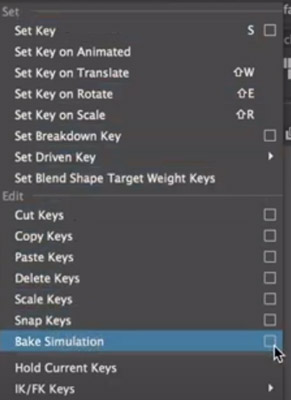
Despite this deceptively easy set of steps, a considerable amount of setup and creative work goes into baking an animation. Additionally, there are several other ways to bake an animation that allow for more customization and refinement of the process.
Options Within the Simulation Editor
There are many sub-options to choose from when exploring the options window for your given simulation. However, most users can generally disregard these sub-options. When doing more complex animations, these options may become necessary. Here we will discuss the various options and what editing them will do to a given animation.
Hierarchy Selection
First is the hierarchy selection that allows you to choose what objects will be set to the keyframes. You can toggle this option to select a group of items under the same parent group.
- Selected: will key only the selected object or objects. You can select objects from outside of the window with the manipulator tool.
- Below: Will key all animations of the selected objects and all those within the group beneath it in the hierarchy.
Channels Option
The channels option allows you to decide which specific animation curves are to be keyed. The channels option provides for a more specific simulation but can lead to errors if channels are not created properly.
- Channels: make specific channels that will be added by MAYA to the key set. Baking individual channels can make for more customization of multiple movements on the same key.
- All Keyable: This is the default and is always on. It makes it so ALL of the selected object’s animation curves are keyed on the simulation.
- From Channel Box: Keysets selected in the channel box window will be the only ones baked. You must ensure that you have curves chosen in the box, as it will default to selecting all of them.
- Driven Channels: Ensures that driven keys within the keyset are animated by the system on the same key. (This is set to off and requires advanced techniques)
Control Points
Control Points makes it so that all control points are animated. You can often see the control point option in a NURBS application (Non-Uniform Rational B- Spline) and their control vertices. In addition to NURBS, it locates any polygonal vertices.
Shapes
Shapes are the default parameter for the channel sub-option. It includes the animations for the selected object’s shape and transform nodes.
Time Range Selector
The time range selector selects how long a particular animation is to be baked and determines its size. This range determines the number of keyframes and results in increased render time for longer animations.
- Time Slider: The default option, it will animate the entire length of the scene. You can edit the time slider’s various parameters by entering the animation panel and changing the time slider options at the bottom.
- Start/End: For use when you want only a specific amount of time to receive the baking treatment. The start time and end time options are greyed out and unavailable until this is selected.
- Start Time: The location on the time slider where the baking process begins.
- End Time: Where the baking process halts.
Baking
“Bake to” allows you to decide what layers MAYA will bake and where to place the results. Base animation is the default and will put the products on your current layer. A new layer makes the baked results appear on a new layer, with anything unbaked left uncopied.
The baked layers option has a dropdown menu providing opportunities for various attributes to be manipulated by you.
- Keep: This option makes all of the object’s attributes stay on the layer.
- Remove Attributes: All of the selected attributes are removed from the animation layers when baked.
- Clear Animation: Animation and keys are removed by the system automatically from the source layers
Sample By
Sample By allows you to edit how often the baking process keys the frames into the time slider. By default, this feature is set by the options to every one frame; however, you can change it to your desired frames here. You can use the tool to fit frame rate specifications or to allow more refined control of movements.
Smart Bake
Smart Bake puts a limit on how many keyframes you bake. This option ensures that the keys are set only at times where the animation curves have a keyframe.
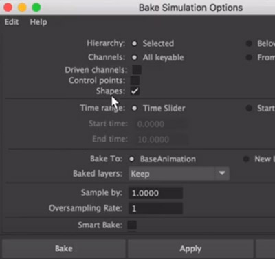
Smart bake helps reduce render times by cutting out redundant keyframes when an animation is idle. It is not particularly useful in most cases and is only for those who want to keep the keys simplified.
Increase Fidelity
Increase fidelity is only available when smart bake is on and functions to add keyframes to the baked result based on your chosen tolerance.
Fidelity Key Tolerance
This tool allows MAYA to add extra keyframes depending on the animation curves present. Depending on the percentage set, the system decides to add additional keyframes, increasing the animation’s smoothness and fidelity.
The lower the key tolerance is, the more keyframes added, with higher tolerances having fewer keyframes. Higher tolerance will allow your result to differentiate more.
Keep Unbaked Keys
Keep unbaked keys will keep the animation that is not within the set time range. When off, the keys outside of the set range will not be present in the baked animation. This option is on by default.
Sparse Curve Bake
Sparse Curve Bake lowers the number of curves you bake during processing, only producing enough keys to represent the original curve. This process only works on the curves that are directly connected.
Disable Implicit Control
Disable implicit control removes the ability to manipulate controls and handles after the process.
Unroll Rotation
Unroll rotation is mostly used by game and film creators in motion capture makes sure that movements cannot exceed 180 degrees of movement between keyframes. This option limits the animation if the capture spaces keys by more than 180 degrees apart.
Baking Inverse Kinematics
Inverse Kinematics or IK is the process of reversing the order in which a hierarchy follows its commands. This feature is used by animators to create more fluid animations as Forward Kinematics (FK) force the entire object to follow its parent command.
Using FK for moving bodies atop a stationary form often results in less fluid and nonsensical animations. Utilizing IK can make the process easier for animators.
You can take Large groups of objects that you can then animate by manipulating a single parent. The use of IK results in a figure being static in some locations while still having independent motion.
A simple example of the use for IK is when placing a character’s foot or leg but allowing for movement of the knees.
When you edit a figure’s hips by moving a parent in the hierarchy, it does not impact the entire leg and foot; instead, the feet stay planted, and the knees bend. By doing animations in this way, they end up looking much more realistic to the human eye.
The process of baking using Inverse Kinematics is simple and utilizes a similar process depending on your need.
- Select the joint and parent hierarchy desired.
- Select the key menu and click on the baking simulation submenu
- Check the disable implicit control box.
- Bake
What is Animation Baking?
The act of baking an animation runs an animation sequence and creates a copy of an object’s movements.
By baking an animation, you can achieve high-quality effects without requiring the computer to render it. An animator’s framing was done by an artist ahead of time, leading to a lesser load on the system. This can also allow for files to be transported between various pieces of software.
Using both simulation and functional processes, baking your animation can save load and render times further down the line. Creating keyed frames for an animation, rather than flowing between more spaced out keyframes, allows the movements to be the same every time.
Due to the inherent randomness brought in by animation, baking an animation layer or key is essential to creating a polished and reliable output.
Baking Animation in the Medical Animation Field
This process has found its niche in the medical animation field where there is a distinct need for motion to be baked to save on rendering time. While the process may seem counterintuitive, creating extra keys when the animation is fluid enough serves a vital function. At the same time, the baking process may initially take more time with rendering the second time.
Every time after that, it will play out faster and to the exact specifications. This conservation of memory is accomplished by reading the baked animation file and memory instead of rendering it thoroughly each time.
You can also bake visual effects using the same process. This allows for things such as smoke, liquids, or particle effects to be pre-rendered. This is especially useful when you are using complex shaders and lights. There is a steep level of rendering time needed to produce more complex animations the can cost you time. This is important for biological dynamics and particle effects simulations that cannot be animated manually by hand, and have to start with a powerful but less controllable simulation.
In the event that you do not bake your animations, you will find difficulties in loading files at a later point. The mistake of not transferring your nodes to keyframes can also result in a file not being read by other programs. Baking animations is a simple yet vital part of the process that cannot be ignored as you scale up your projects.
Exporting an Animation Layer
When exporting a particular animation for Unity or similar programs, the animation layer can be baked by the computer immediately upon export. This feature can save time and provides a crucial step for using the file with any animation.
An unbaked file does not have the nodes determined and locked to keyframes, making it often not work with other programs.
Suppose more finely tuned animation baking is required. In that case, it is not recommended by professionals to bake upon export as doing so uses the default settings.
The best use for this process is to create something with Inverse Kinematics or to bake at different intervals. In that case, I recommend baking your animation ahead of time. You can do this by referring to the directions at the beginning of this guide.
The actual process of exporting a MAYA animation to FBX for further use is relatively simple.
- Go to file and then export selection, choosing FBX as the file type, or go, game exporter, if your version of MAYA allows for it (this will automatically use an FBX file)
- MAYA will present you with a prompt with several options for exporting your file. Most of these are self-explanatory and are commonly left alone unless required for specific circumstances.
- Suppose you are choosing to bake upon export. In that case, the submenu is in the location, and you should be toggling it before exporting.
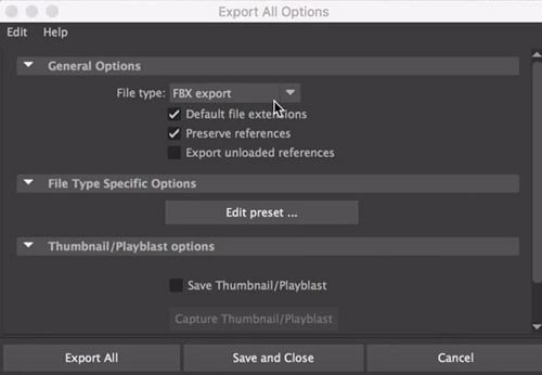
FBX Files
There are a number of programs that will read the FBX file, which stands for filmbox, and even a few that allow for direct manipulation of the animation. These programs include the following:
- Unity: A cross platform game engine that is used by many developers to create applications for PC and Mac. Unity cannot accept the animation files without them first being baked, as importing a regular MAYA file will just result in the objects being brought over.
- Autodesk Auto CAD: Computer-Aided Design (CAD) software made by the same developers as MAYA. AutoCAD is used primarily for engineering, design, or manufacturing processes and offers robust simulation and 3D printing software.
- Unreal Engine: 2D and 3D animation software created by Epic for use with game and simulation development.
- Mudbox: A program used primarily for sculpting 3D objects and baking textures into files. This is used in animation to mostly fix an error or to create UV mesh to go atop an object.
Examples of Baked Animations
Any animation used in a loop or for the purpose of fine-tuning down to the specific frame will use baking techniques.
Walking and idle animations are often used, frequently acting as a baseline for a character or object. Having these pre-made permits them to be interrupted at any keyframe allowing for a smoother transition between actions.
Baking your animations is essential for any application used for the creation of video games. For example, Unity’s programming suite is popular with mostly independent developers. It requires the keys to be set for Unity ahead of time.
The requirement to have keys is because MAYA utilizes nodes and a hierarchy that does not translate well to other programs easily.
What Types of Animation are Supported by MAYA?
There are many different animating methods in MAYA that will affect your workflow and determine the parameters that you can edit. The most common techniques for animating are keyframe animation, nonlinear animation, importing of motion capture files, and layered animation.
- Keyframe Animation: The most common application of MAYA’s animation capabilities, keyframe animation, lets you move the objects of your animation in time by setting keyframes on a timeline.
- Nonlinear animation: Lets you use various clips of animation in any order allowing for you to achieve new effects. Nonlinear animation is most common in looping animations such as a walk cycle or idle stance that repeats.
- Motion Capture: Maya has the ability to accept data from a motion capture session. This allows for believable and dynamic motion that can have a large impact.
- Layered Animation- Saving your animation into layers can improve workflow and productivity. The layered animation choice lets you combine and change motions on a large scale.
- Path Animation: Sets the object to move upon a predetermined curve. This style of animation makes it so the object follows the curve the same each time.
- Dynamic Animation: Utilizing dynamic animation allows you to create things with natural effects. The effects created by this style are subject to the forces of nature, such as gravity or conservation of energy (Ex. things falling or bouncing off vessel walls)
No matter how you choose to animate, you can bake all of the products into simple keyframes for export or minute adjustment. It is imperative to acknowledge the various animation styles as some excel in ways others do not.
Here is a good video by Autodesk on baking and exporting animation :
Texture Baking in Maya
While an animator can bake animations to create a modifiable, faster rendering output, you can bake textures to aid in the rendering and animation process as well.
Baking textures allows you to place them on a set of UV coordinates rather than rendering them in real-time which can lead to unexpected results.
Artists primarily use this to save the colors, reflections, and shadows cast by lights in a scene. Baking a texture map can be used to be later added onto objects. It saves on workflow, allowing animators and artists to share files more easily. It also saves on computing power, doing the initial work ahead of time, and not during final rendering.
The steps to baking a texture in MAYA are similar to baking animation, with the user interface changing between the two modes.
- Open the windows sub-menu, selecting Material/Texture baking editor, and finally, texture baking settings.
- Opening up the settings window allows the various settings to be adjusted, with minimal sample rate being at least 0 and max at least a value of 2.
Final Thoughts
The act of baking can turn relatively complex animations into much more simple and easy to manage files. It is a vital component of creating smooth and well-defined animations. The consistency of the simulation when an animation is baked allows for other aspects to be freely worked on. It is vital for you and any other animator to learn these basic steps to create more efficient animations.
The animation of 3D objects is a complex and often underappreciated art that comes with many challenges. One of these challenges is the flexibility of various aspects of a given simulation. When aspects such as collision and gravity come into play, there can be many possible outcomes.
When you bake things down and specify their various keyframes, you ensure that the finished product is the same every time. This constant result can become the linchpin of realistic animation.
Click the following link to learn the difference between trax editor and time editor.