
When I first dipped my toes into the world of 3D design, 3d scan to CAD was like an alien language. It felt as though I’d stepped onto a foreign planet, full of complex parts and dense point clouds. I remember holding that handheld scanner for the first time – it was both intimidating and exhilarating. But with each scanned object, something magical happened: flat surfaces came alive in intricate detail; organic forms were captured with precision unseen by human eyes. Suddenly, reverse engineering wasn’t just possible – it became a thrilling journey from physical objects to digital reality.
In this article I will lead you towards more efficient and creative ways of working with 3D scans in CAD modeling. In medical device design/redesign and even medical animation, this is very useful.
The Magic of Reverse Engineering Software
Let us look at what makes reverse engineering special and extremely useful. The beauty lies not only in creating new designs but also retrofitting existing parts through reverse engineering—a vital part of building solid CAD (Computer-aided design) models today. Many industries use these techniques extensively because they make replication and variation creation faster compared to designing something entirely new every time—time is money after all.
Create Accurate Foundation For New Designs
-
Digital twins: With detailed 3D scans, we can create accurate digital twins of physical objects. These serve as a reliable reference for creating new designs.
-
Custom parts: Scan data usable in CAD software lets us easily modify the original design to fit our specific needs or constraints.
-
Improved workflow: By weaving the scan-to-CAD process into your existing workflows, you can cut down on time and boost efficiency. This integration helps to streamline operations, making things run more smoothly in the long haul.
Understanding the 3D Scan to CAD Process
The journey from a physical object to an editable, digital model in your preferred CAD software can seem daunting. But fear not. We’re here to break down the process and shed some light on how this magic happens digitally.
Digitizing Physical Objects with 3D Scanning
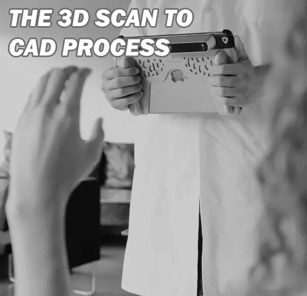
To start, you need a good quality scan of your existing object. Using a handheld 3D scanner, you’ll capture all the complex parts and organic surfaces of your subject into what’s known as point cloud data.
This raw scanner output acts like a very detailed distance meter for every surface geometry detail on your scanned object. The result? A dense blanket of points that accurately represent the shape and size of the original part – think of it as laying down dots over every contour until you have an accurate foundation for further work.
Making Scan Data Usable: Converting Point Clouds into Meshes
Once we’ve got our initial scans complete, there’s more work before we create CAD models from these captures. This next stage is about turning those billions (yes, often billions) of points captured by our trusty 3d scanner into something more manageable – usually triangles forming polygons or meshes.
A lot happens at this modeling stage; filling holes where scanning might have missed out details or creating surfaces over gaps where no data exists are just some examples.
Creating Your Final CAD Model: Reverse Engineering Software Magic
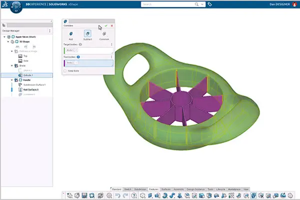
Now comes perhaps one of the most exciting parts—converting scan data usable within our chosen CAD software using reverse engineering tools such as Mesh2Surface for SOLIDWORKS.
This CAD reverse engineering process is where we transform our mesh into a solid CAD model. This transformation from scan-to-CAD software involves creating accurate and editable features that reflect the scanned object’s surface properties.
Adding Details and Refining the Design
In wrapping up this 3D scan to CAD short process outline, we focus on refining the minute details. It is essential to make sure all components are perfectly lined up, particularly if they form a larger assembly. Sometimes, tweaking is needed for an optimal fit.
Techniques and Tools for 3D Scanning
From physical object to CAD model, 3D scanning provides the solution. Different scanners are used in various ways depending on the project.
Choosing the Right Scanning Tools for Your Project
The first step is choosing your weapon of choice – that’s right, your 3D scanner. It’s like picking out a new car: it needs to suit your style but also perform under pressure. Handheld scanners can be overwhelming because there’s so much to offer.
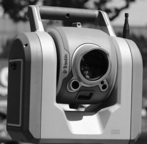
You need something versatile enough to capture complex parts with ease and precision. Consider this; if our task were scanning a tree (hello organic surfaces), would you use the same tools as when scanning say…an engine part? Probably not.
A key tip here is understanding what each scanner outputs before diving into purchase mode. Some spit out dense triangle mesh data in obj format while others prefer ply or stl mesh formats.
Best Practices for Scanning Complex Parts and Organic Surfaces
Navigating through this process isn’t just about having the right gear; it’s knowing how to use it too.
-
Ensure the scanner is positioned correctly relative to the object – not too near or far away, otherwise your scan results may appear like a work of art. Too close or too far, and your scan data could end up looking like abstract art.
-
Next, we ensure our scanning tools are properly calibrated. It’s kind of like tuning a guitar – you need to get it just right before you start playing.
-
We then commence with our 3D scans in sections, working methodically around each part of the object.
The best part is that digital technology can help us recreate existing parts. It’s like we’re turning back time.
Converting Scan Data into CAD Models
Scan data alone doesn’t give us editable features; we need help converting it into something usable like SolidWorks CAD entities or Autodesk Inventor surfaces. This is where reverse engineering software steps in. Using these tools allows engineers not just to recreate an exact copy but also to modify and improve upon scanned items without extra time designing from scratch.
The journey from 3D scan data to a final, usable solid CAD model might seem complex. But with the right approach and tools it becomes an efficient process.
Filling Holes and Repairing Meshes in Scan Data
Once you have your scanned object’s surface geometry represented as point cloud data, it’s time to convert this raw scanner output into something more manageable, like a mesh. That will finally be converted into solid, which is what CAD programs use. A common issue is holes in the mesh due to scanning limitations or complex parts of the physical objects being missed by the scanner.
To create accurate foundations for our CAD models, these gaps need fixing before moving onto any further steps. With advanced software filling holes can be done seamlessly – ensuring that we’re not just working on a blank canvas but one that accurately represents our existing object. This helps us get closer to creating solid CAD models from our scans – turning what was once simply visual information into editable features within our preferred CAD software environment.
Software such as SOLIDWORKS or RHINOCEROS include options to clean up scan data. SCANTO3D is a tool for SOLIDWORKS that has many helpful features for this process, it has wizards to help you go from a scanned point cloud to a mesh and to go from a mesh to a solid model which is needed for CAD (unlike just a hollow mesh for animation software like Maya). We want our solid model (click here for detailed definition) to be ready for use.
MeshLab is a free open source software that allows fixing of holes and converting it into a file type such as STL, which is a triangle mesh file used in 3D printing.
We also have tools such as Geomagic Design X at our disposal which help make scan data usable within preferred CAD software platforms like SolidWorks or Autodesk Inventor.
Speaking of other popular options in CAD modeling, Autodesk Inventor deserves a mention too. Known for its superior performance in creating mechanical designs, Autodesk is highly recommended by many professionals involved in product development due to its intuitive user interface and vast array of design capabilities.
Control Points and Surface Measurements: Creating Your Final CAD Model
In order to successfully reverse engineer existing parts or build new designs based on real-world objects, control points are highly recommended during this phase of converting scan data into usable form. These act as markers which guide how surfaces are shaped during the modeling stage of building your final CAD model.
But setting control points isn’t enough; software capturing accurate surface measurements also plays a critical role in developing high-quality CAD models. By meticulously recording each measurement down to even minute details such as fillets or small embossed text ensures nothing gets lost in translation when moving from physical world scanning towards digital design.
This is where the real power of scan-to-CAD software like SolidWorks CAD comes into play. They allow you to convert scanner data directly into CAD entities – making your reverse engineering or design process a lot more streamlined and accurate.
Case Studies on Successful Integration of Scan to CAD Workflow
Every industry, from aerospace to medical, can reap the benefits of a well-integrated scan-to-CAD workflow. Let’s take a deeper dive into some actual scenarios where businesses have efficiently used these technologies.
Enhancing CAD Workflow with Autodesk Inventor and Other Tools
The automotive industry has been quick to adopt 3D scanning and CAD software in their design processes. For instance, an auto parts manufacturer was faced with the challenge of reverse engineering complex parts for high-performance vehicles. Their goal? Create accurate CAD models that would allow them to enhance product performance while reducing production time.
This is where Autodesk Inventor, along with other scanning tools like Geomagic Design X, came into play. By combining the strengths of these powerful applications, they were able not only to capture every detail but also convert this data into editable features within their preferred CAD software.
The result? The final CAD model was so precise it felt as though you could almost hear the roar of its engine.
Filling Holes: A Construction Case Study
In another case study involving construction retrofit projects, often requires exact measurements which are hard if not impossible using traditional distance meters or tapes alone; enter 3D scanners. These devices captured highly detailed scans down to each millimeter, making scan data usable by architects in creating perfect-fit solutions for existing structures.
Solidifying Success with SolidWorks Plugin
The SolidWorks plugin allowed engineers to convert scan data into solid CAD entities seamlessly without losing any surface geometry details, building CAD models that fit like a glove.
The SolidWorks CAD process also saved them countless hours they would have otherwise spent measuring and drawing on a blank canvas. This case is an excellent demonstration of how scanning tools can enhance workflow efficiency in the construction industry, providing architects with an accurate foundation to work from.
FAQs
Can you scan an object into CAD?
Absolutely. 3D scanners capture the geometry of physical objects, creating a point cloud or mesh that can be converted into a CAD model.
How to convert 3D scan to 3D model?
You use software like SOLIDWORKS or Mesh2Surface plugin to turn your scanned data into precise, manipulable 3D models.
How do I import scan data into Solidworks?
To bring in your scanned info, open SOLIDWORKS and click ‘Open’. Select the file type for your scanning output then choose the desired file.
Can you 3D print from a scan?
Sure thing. Once an object is digitally captured with a scanner and converted into STL format, it’s ready for additive manufacturing – aka: “printing”.
Conclusion
Stepping into the world of 3d scan to CAD can feel like landing on an alien planet. But, as you’ve discovered, it’s a journey filled with discovery and innovation. The magic happens when we transform physical objects into precise digital models using 3D scanners. It opens up new avenues for reverse engineering that were once unthinkable.
Different scanning techniques offer unique advantages while software solutions help optimize scan data usability. Building accurate CAD models from this scanned data becomes our reality rather than starting from scratch each time.
The future? Expect more advances in 3D scanning technology making reverse engineering even more efficient and creative. Click the following link to learn how to 3D print from MRI or CT scans.
Recent Posts
Mastering point cloud to 3d model conversion can feel like translating whispers from another dimension into vivid sculptures. You've got this cloud of data points, a chaotic concert of coordinates...
Let's say you've got a drawing, something you sketched out during a burst of inspiration, and now you're itching to see it leap off the page into three dimensions. Well, that’s exactly what I did...